


Blade VS+

Saber 4K+
Saber X
Saber U20

Saber Plus
Saber IP20X
Saber Light
Saber 4K+ NDI®
Saber IP20X NDI®

Blade 4K
Saber 4K
Saber AT

Cleartalk Wired ASP-05

Cleartalk HD ASP-10

Cleartalk Wireless ASP-04

Cleartalk Anchor ASP-06

Cleartalk DC 4 Units ASP-04D-4S
Ceiling Mic Pro ASP-C-01

Ceiling Mic Pro ASP-C-02

Ceiling Mic QS ASP-C-04

Cleartalk DC 2 units ASP-04D-2

Cleartalk HD DC ASP-10D-2
Mission Control Keyboard
Wall Bracket (White)
Wall Bracket (Black)
USB3.0 Extend Cable 10-30M
USB3.0 A male to B male Active Optical Cable
USB3.1 Type A-C Active Optical Cable
HDMI 2.0 Cable
Ceiling Mount (White)
Ceiling Mount (Black)
USB2.0 Extender
One Touch Wall Bracket (Black)
IP Controller
Remote Control for Saber and Blade
Cord Cover Wall Bracket (Black)
Remote Control for One Touch
Cord Cover Wall Bracket (White)
RS232 Cable
RS232 Joystick
Power Adapter

Blogs
Mission Control Keyboard Advanced Tutorial
Mission Control Keyboard Advanced Tutorial
While you can access just about every feature on your Angekis Camera using the included remote control, for high level productions a joystick controller is a must-have PTZ control accessory.
The Angekis Mission Control Keyboard is an excellent choice for professional camera control and![]() video production. If you’re really a professional, you can even figure out how to buy it starting here: [https://www.angekis.com/product_detail/Mission%E2%80%94Control%E2%80%94Keyboard.html]
video production. If you’re really a professional, you can even figure out how to buy it starting here: [https://www.angekis.com/product_detail/Mission%E2%80%94Control%E2%80%94Keyboard.html]
This PTZ Control Keyboard gives you precision control over all of your cameras with a responsive and accurate joystick. The keyboard itself is a quick and comfortable way to access granular control over camera settings, and can be programmed to connect with up to 7 cameras at a time, while the built-in 3.12-inch OLED screen gives you need to know information at a glance. It’s perfect for advanced videoconferencing, live broadcasting, video recording, and any scenario where you’ll be using PTZ cameras.
Let’s take a look at the interface, how to set it up, and how to use it!

1.0 Interface Description
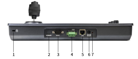
1. Lock Hole 2. Upgrade Interface 3. RS232 Interface 4. RS485 Interface 5. Network Interface 6. Power Interface 7. Indicator Light 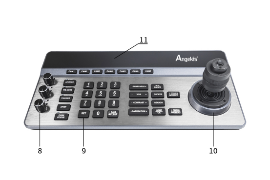
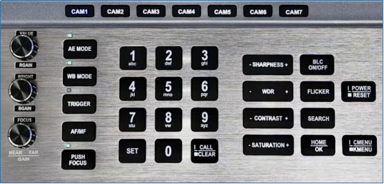
8. Adjustment Knobs 9. Buttons 10. Joystick 11. Display
2.0 Connection Modes
The Mission Control keyboard can be connected either through IP (meaning you use RJ45/Ethernet cables to connect to a LAN) or using RS-232 to Daisy Chain the cameras directly to the Keyboard.
2.1 Connection in Network Control Mode (IP): This means you’re using the camera’s IP Address to connect to the keyboard over a LAN.
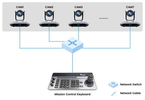
Both the keyboard and camera[s] should be connected to the same LAN and remain on the same network segment.
e.g.:IP address of the Mission Control keyboard is 192.168.1.188, the IP address of Camera 1 is 192.168.1.189, and the IP address of Camera 2 is 192.168.1.201
2.2 Connection in RS-232 Mode: This means you’re using RS-232 cables to link the cameras together and finally to the keyboard.
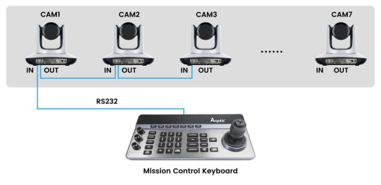
Connect the RS-232 interface of the keyboard and the RS-232 IN port of the camera using the normal RS-232 control cable, provided in the box with most Angekis cameras. Up to 7 cameras can be connected using RS-232 control cables via daisy chaining.
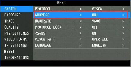
Each camera must have its Camera Address Code changed to an address between 1 and 7. The Camera Address Code is not the same as the device IP address. You can change each camera’s address code by using the OSD menu. Go into the OSD menu with the remote control, then SYSTEM > ADDRESS and here change the Camera Address Code to a number between 001 and 007.
3.0 Set Up Guide
3.1 Menu
Long press [CMENU/KMENU]to open the keyboard menu. Move the joystick up and down to view the menu options. Go right to enter the next option, go left to return to the previous option.
Short pressing [CMENU/KMENU] will also return to the previous option. Numeric keys 0 to 9 can be used to set parameters in some options.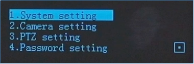
3.2 Connection Configuration
3.2.1 Internet
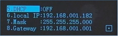
Keyboard IP configuration
Long press [CMENU/KMENU] to open the menu;choose “1. System Setting”, and go down to change the IP setting of the keyboard itself.
Configuration for binding cameras to the CAM keys over IP:
Long press [CMENU/KMENU] to open the menu, choose “2. Camera Setting”, to get into the camera setting page.
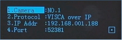
Camera:Camera Address Code. NO.1 stands for CAM1. You can switch to another camera by pressing Up or Down.
Protocol:Control Protocol. Available options are: Pelco-P, Pelco-D, VISCA over IP, VISCA TCP, VISCA UDP, ONVIF, and NDI. VISCA over IP is our recommended default.
IP Addr:The current IP address of the selected camera.
Port:Communication port number. Default port number of each IP protocol:ONVIF: 8000, NDI: 5961, VISCA: 52381
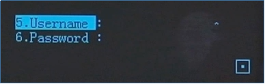
Username:User name setting. The default is:admin
Password: Password corresponding with the user name. The default is:admin
3.2.2 Serial Port Connection Configuration
Configuration for binding cameras to the CAM keys over Serial:
Long press [CMENU/KMENU] to open the menu;choose “2. Camera settings”, to get into the camera settings page.
Camera:Camera key number. NO.1 stands for CAM1. You can change this using the joystick.
Protocol:Control Protocol. Choose VISCA Serial.
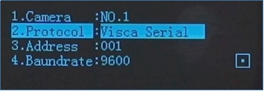
Address: Camera address code. You can modify this through the OSD menu of the camera with the remote control.
Baud rate: Baud rate. Default 9600.
3.3 Basic Functions of the Keyboard
3.3.1 Shortcut Selection
Press [CAM1]~[CAM7] to select the corresponding camera.

3.3.2 Joystick Control
[Up] [Down] [Left] [Right] Move the joystick to control the camera. If you don’t already know how to use this I genuinely do not know how you made it this far in life.
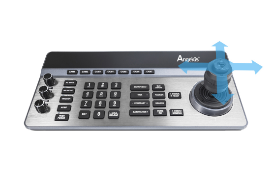
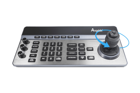
[Zoom +] Turn the joystick clockwise to zoom in.
[Zoom -] Turn the joystick counterclockwise to zoom out.
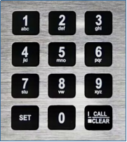
3.3.3 Preset Setting
[0]~[9]+[SET] Set the preset.
[0]~[9]+ short press[CALL/CLEAR] call the preset.
[0]~[9]+ long press[CALL/CLEAR] clear the preset.
Note: up to 128 presets can be set and recalled per camera.
3.3.4 Parameter Adjustment Area
[-SHARPNESS+] ] Adjust the sharpness.
[-WDR+] Adjust the WDR.
[-CONTRAST+] Adjust the contrast.
[-SATURATION+] Adjust the saturation.
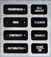
3.3.5 Other Button Areas
[BLC ON/OFF]Backlight compensation on / off.
[FLICKER] Anti-Flicker switching.
[SEARCH] Search for IP addresses on the network.
[HOME/OK] Return to the original position of the camera.
[POWER/RESET] Short press to control the camera power, long press to reset the camera. [CMENU/KMENU] Short press to open the camera menu, long press to open the keyboard menu.
4.0 FAQ
4.1 What if I do not know the control interface of the Camera?
We support LAN interfaces, RS232 interfaces, RS422 interfaces and RS485 interface control. The Mission Control Keyboard is adaptable to just about any control interface, so we recommend plugging it in and trying whatever option might be available.
4.2 What can I do if there are multiple cameras with different control ports?
We support up to 7 cameras with seven buttons (CAM1, CAM2, etc.) and each one can be controlled using different control interfaces and protocols. They do not all need to use the same protocol. The Mission Control Keyboard supports control over VISCA Serial, Pelco-P, Pelco-D, VISCA over IP, Visca TCP, Visca UDP, ONVIF, and NDI. [NDI is optional.]
4.3 Can I control more than 7 cameras?
Yes you can! This method requires a little bit of planning, but you can easily add a large number of cameras by using an IP address trick. Using the keypad, enter the a string of 3 digits that correspond to the last 3 digits of the unconnected camera’s IP address. Then press [CAM#]. This will quickly reprogram that CAM button to control the device correlated with that IP address. For example, if the IP address of a camera is 192.168.1.188, enter "188" on the keyboard and select "CAM 7". Now CAM 7 will control the camera at the address 192.168.1.188. If you use this trick we suggest only using CAM7 and making sure you have a written or printed copy of the IP addresses for all cameras on your local network. Also note that the last 3 digits of IP addresses are limited to numbers below 256.